What am I Doing?
A few months ago, my friend approached me and asked if I could put a Polarstar Jack into an Echo1 Gat. I foolishly said yes, this would prove harder than I ever anticipated. Fair warning, following the guide below will ruin several pieces of the gun for use as an AEG. Also, this guide will be as much about how I did it as what I did so that anyone can replicate the work if they want to.
The basics
OK… to start off with there are a few things that you need to know about the gat.
- The nozzle is offset
what this means is that you will need a Polarstar F2 or Wolverine Hydra to install the engine in the OEM gearbox. An engine with only a centerline nozzle will not work. This was probably the most challenging thing that I had to deal with. I used an F2, and Polarstar could not reasonably custom mill me a one off nozzle for the gat and either did not have or would not give me measurements, so I was forced to do that part on my own. - You will need to destructively modify some parts
The gearbox as well as the selector toggle/cutoff lever need to be modified to allow the system to work correctly. A screw hole will need to be removed from the front of the gearbox to install the engine and based on the way I did the trigger, I needed to remove part of the selector toggle to allow the custom trigger switch to be installed. - some soldering required
The final thing before I move on to the process is that I had to use custom trigger and selector switches as Polarstar does not have a switchboard for the gat. To do this I used the universal trigger board that comes with the M249 version of the F2. This did require me to crimp some JST connectors to the trigger leads as the kit that I got did not come with two sets of leads and the one that it came with was pretty thick and I was worried it would be crushed in the gearbox.
OK, now that that is out of the way, on to the guide. Pictures are at the bottom.
The Nozzle
Like I said above, the nozzle was probably the most difficult part to get correct. Once I figured out that it was offset and my jack would not suffice, I had to figure out the offset. To do this, I used a flatbed scanner and scanned the original cylinder head from the gearbox and then imported the image into Fusion 360 scaling it to the Pixels Per Inch that I had set the scanner to. I then used the picture as a guide to place circles for the outside of the cylinder wall and the nozzle hole, and then measured those in Fusion to give me my offset. The offset I ended up with was 2.046mm off center. Once I got that out of the way, I took the rest of the measurements from an existing F2 nozzle except the length which I got from the OEM nozzle. The only dimension that I could not get is the thread pitch and diameter for the hole that attaches to the “mid nozzle” or the grey piece that goes through the cap of the F2. That thread was 9/32-32tpi and I could not get that thread in Fusion. In the end, I bought a tap here and just cut the hole to 1/4″ in Fusion and then tapped it by hand when it was done printing. Once I did that, the threads worked perfectly.
Honestly, the part of this that caused me the most grief was the threads, Fusion did not have them and I had a bear of a time finding that tap. If you want the nozzle file or a completed nozzle, shoot me an email and we can work something out.
The Trigger
The trigger was the next thing that I had to work on. As this was an AEG, the trigger was a basic sled design that left a lot to be desired and was quite large. I wanted a microswitch trigger and I also wanted the fire selector to work. I started with a base that attached using the screw that the original trigger contacts attached with.
Once I had this, I figured out that I can use part of the cutoff lever to actuate a microswitch up near the front of the gearbox and with the trigger design that I had, I could easily put the trigger switch itself towards the back of the gearbox.
The last thing to determine was the way to return the trigger. I personally dislike springs for triggers as I feel that any spring with a snappy enough reset is too heavy to fire rapidly and magnets are fun, so I used two magnets that repel each other to reset the trigger. One in the trigger and one in a sled in the trigger board. I originally had several places that the trigger could be placed however after I test fit with the air line for the F2, I realized that there was not enough room for that. I ended up having to bend the actuation arm for the trigger switch to lower the contact point so that you didn’t have to bottom out the trigger to fire it. I also could not get the selector switch to sit down far enough to contact the cutoff lever bit that I was using to actuate it, so I had to print a small chip to allow the switch to be contacted. The chip never quite printed right as it is very small, but I ended up using a touch of superglue and it works just fine.
I also had to cut off a small piece of the cutoff lever near the back of the gearbox to allow my plate to sit flat. The last thing that I did is use a piece of 3mm carbon fiber rod as an axle for the trigger to avoid premature wear and breakage on a printed axle.
Fitting everything together
To fit it all together, the first thing that had to go is the screw hole near the front of the cylinder. I tried to dremel it off first, but it was taking a while and as the gearbox appears to be aluminum the dremel was spinning too fast and ruining tools. I have a 3018 CNC router that I got from amazon that can be set to low RPM and I ended up setting that to 500 RPM and using an endmill to get the protrusion off both halves of the gearbox.
With that done, I test fit the F2 and found that the little nub that ensures the cylinder head aligns correctly was too large to fit in the holes of the F2. To fix this, I used a 4mm hole punch that I have and just punched it down to fit. I also had to dremel a part of the cutoff lever to allow my trigger plate to fit and finally a section out of the back of the gearbox to allow the FCU connection wires out as I wired this gun to a stock from a Krytac SDP.
With all the dremeling out of the way, all the parts basically fit right in. My switch plate fit and bolted right in to place and the trigger slid nicely right into the hole where the OEM trigger fit. I stuck the universal trigger board to the gearbox with a bit of double sided foam tape right near the back beside the rear pin hole and wired everything up.
To wire it together you can use the solenoid wires that come with the F2, and if you got the 249 version you can use the trigger wire that comes with it. However if you want to have a working selector you will need to crimp your own fire selector switch wires. The connectors for the switches and the board side of the noid wires are JST-PH connectors Digikey P/N:455-1165-ND and you will need the appropriate contacts as well (Digikey P/N:455-2148-1-ND). The Solenoid side of the wires if you choose to do that are JST-ZH connectors P/N:455-1366-ND and P/N:455-1130-1-ND for connectors. Once all these wires were crimped, soldered, and connected I tested it and then closed it all up and put it in the body.
The final few mods I had to do were to cut a hole in the bottom of the grip to run the air line and out the back of the body to run the FCU wires. The ridge on the back of the body of the gun was mostly removed by the previous owner to fit an M4 stock, but I was able use what ridges were left to align a 3d printed bracket to mount the SDP stock.
The Stock
The stock that my buddy wanted attached was a Krytac SDP stock. This stock fits on a normal AEG buffer tube mounting extrusion and bolts into the gearbox through a hole in the back of the gun. To attach this I simply designed a piece to sit between the stock and the body and use the existing raised sections on the back of the body to ensure that it aligns correctly. Once I did that, I just had to ensure that the arms for the stock could slide by the bracket and along the sides of the gun. for the arms to slide along the sides of the gun, I had to dremel out channels through the body. Unfortunately, the body is thin and I breached the side of it. I JB-Welded it to make sure there were no holes, but it still looks ugly and I need to find a solution.
Conclusion
This was a very interesting project and I thoroughly enjoyed working through the puzzles that it created. I posted this here with the intent of documenting what I did so that if someone else wants to they can replicate my work. I will not be providing the models for free as the time and effort I put into them I feel warrants some return on investment. If you would like them, email me and we can work something out. If you want to do this but do not have access to a 3d printer, I will also ship you copies of the models for a reasonable price. Just be warned that you will still need access to a dremel or a router/mill and some patience. If you just want to keep an eye on further development of this project, I will try to keep it up to date. I have a few things that I would still like to work out now that it is functional.
- Trigger Adjustability
The trigger is currently not adjustable. I want to make it adjustable so that the shooter can tune it to their liking. This will likely require a rebuild of the trigger board as well as possibly a redesign of the trigger reset mechanism. - Safety
The safety does not work. The bar that engages the safety lever is part of the trigger and not strong enough to sustain use. This needs to be fixed. - Barrel Shroud Tube
The current barrel shroud is heavy and kinda looks ugly as the previous owner swiss-cheesed it in an attempt to add an optics rail. I would like to design and print a new handguard that looks better as well as having a top and bottom rail to add optics to.
If you got this far, thanks for reading! I did this mostly for fun and because I enjoy stupid stuff like this. If you have any questions, my email is below.

finished product 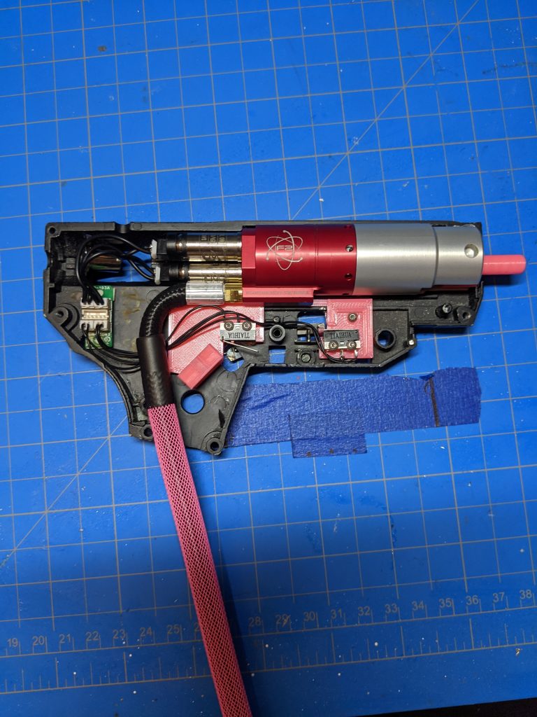
inside the gearbox with everything in place 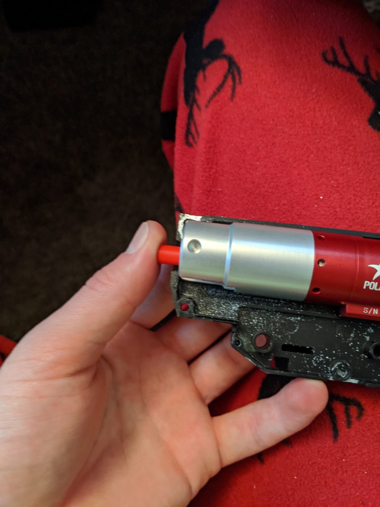
testing fitment of the F2 with the custom nozzle 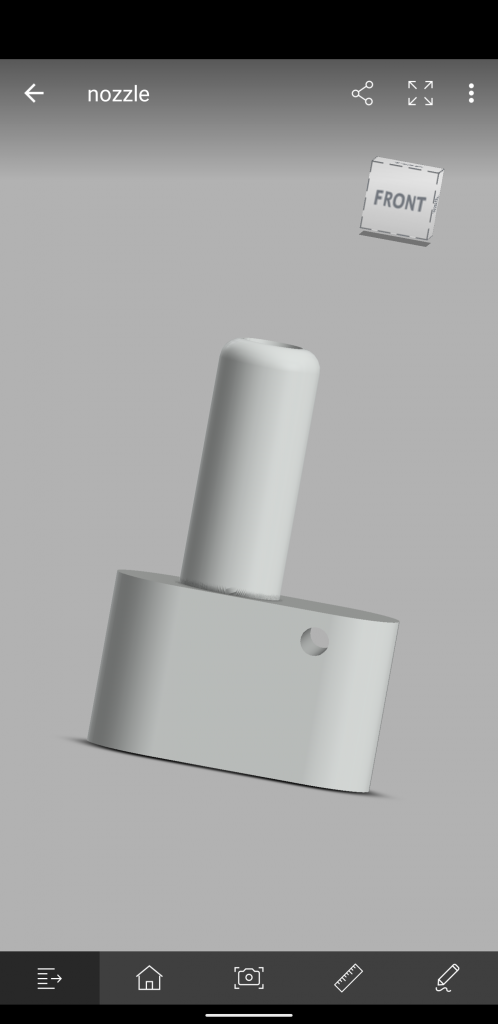
nozzle model 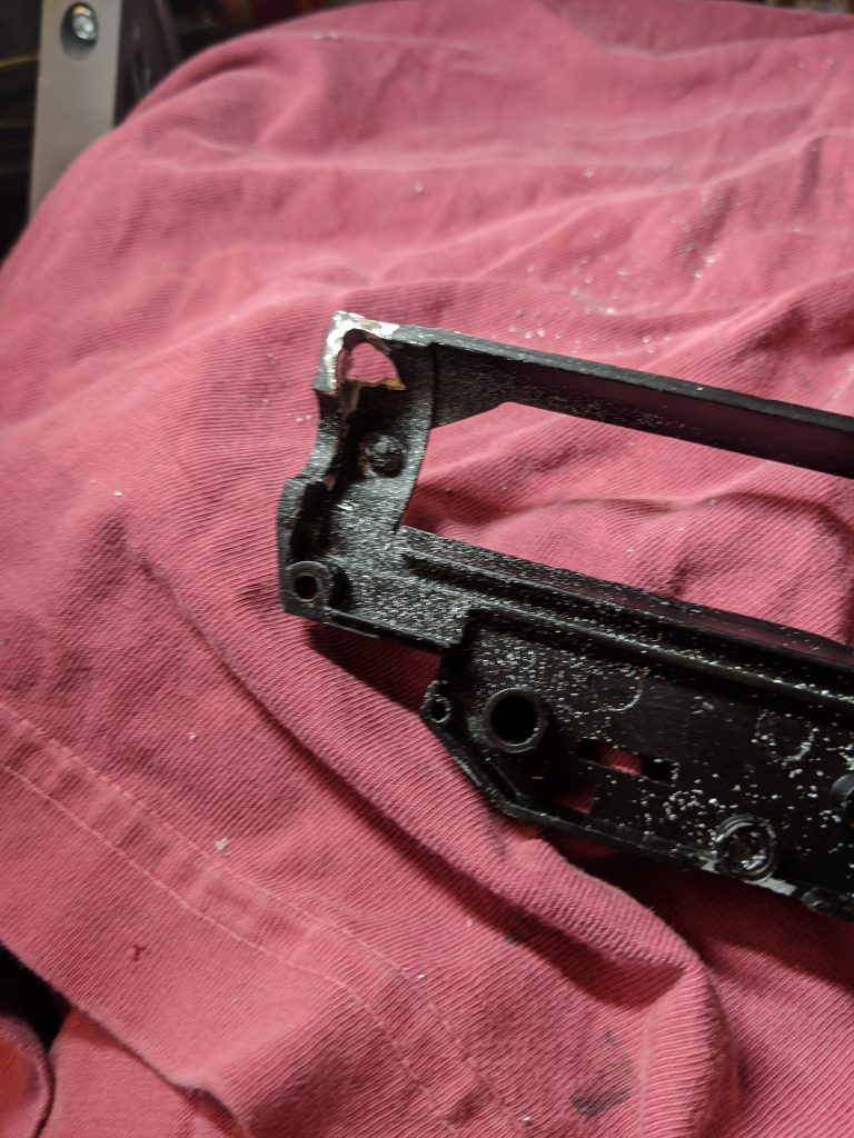
removing the threaded stud from the front of the gearbox 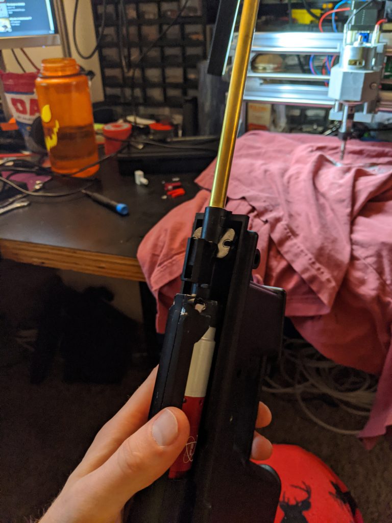
view from outside the gearbox, notice the holes in the top of the gearbox shell where I removed the screw posts 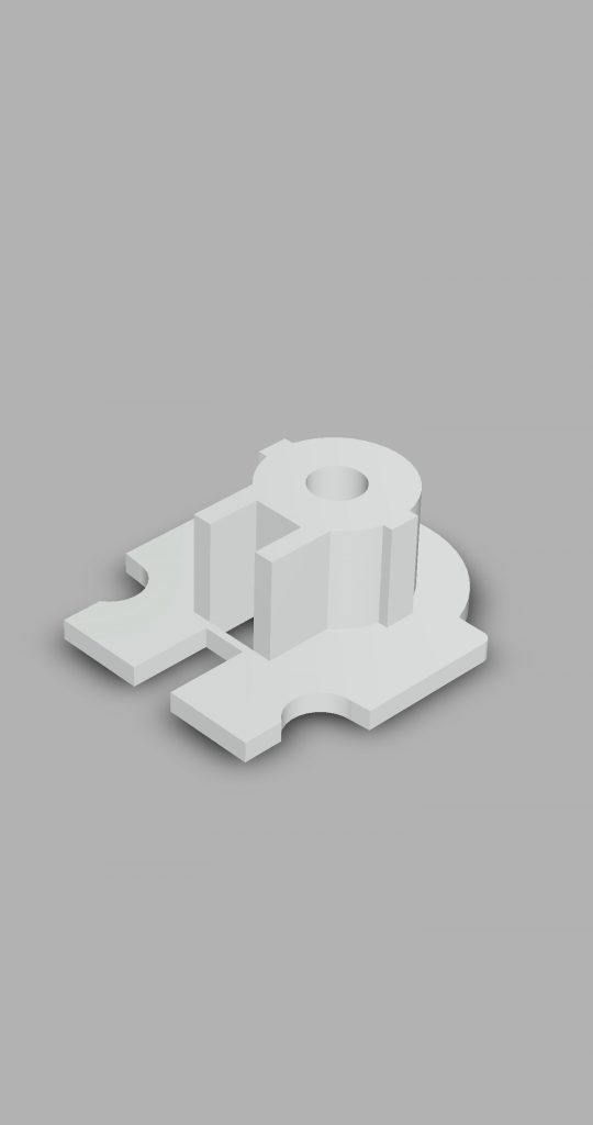
the stock adapter model 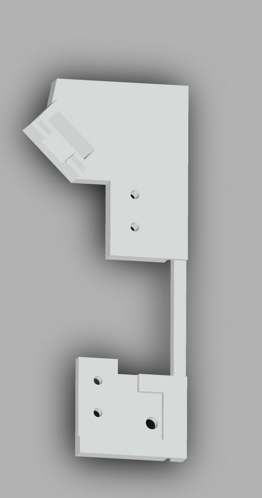
“trigger board” model 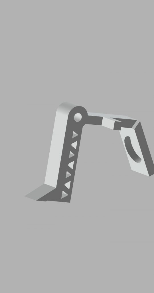
trigger model 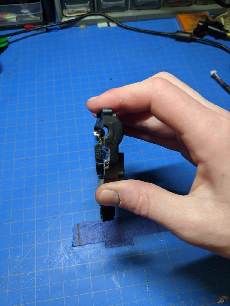
rear view of the hole for the FCU wires 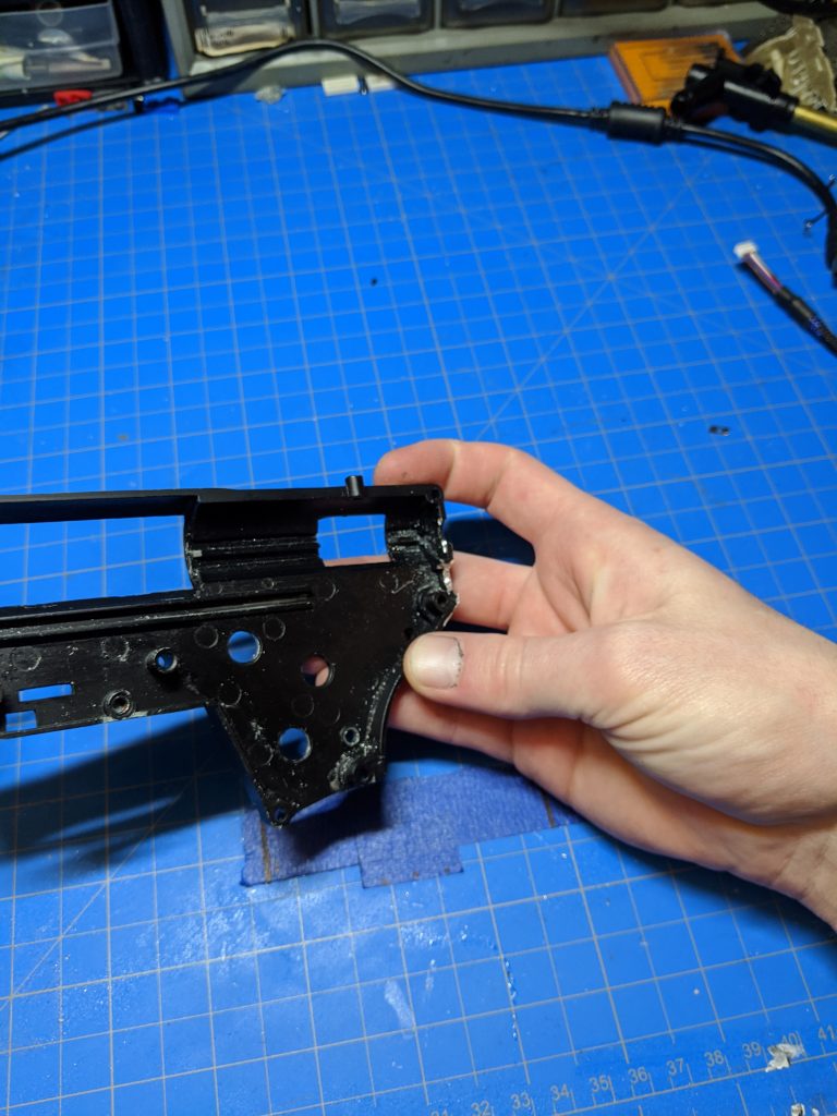
side view of the hole for FCU wires